IFMA Logo

This paper will provide insight on how to properly size pumps in a distributed network, as well as addressing some of the most common questions and selection pitfalls. The focus systems of this paper are chilled water, but the same theories will apply for hydronic heating, as well.

GRUNDFOS DISTRIBUTED PUMPING WHITE PAPER

PUMP SIZING IN A DISTRIBUTED PUMPING SYSTEM

By: Pavel Mirchev, CBS Senior Sales Engineer, Grundfos USA

Introduction

Chilled water hydronic applications traditionally have been arranged two ways; primary with variable secondary, or variable primary pumps. Distributed pumping is an introduction of a third style of hydronic pumping.

This paper will provide insight on how to properly size pumps in a distributed network, as well as addressing some of the most common questions and selection pitfalls. The focus systems of this paper are chilled water, but the same theories will apply for hydronic heating, as well.

To understand the subject matter of this paper, it is necessary to understand pump and hydraulic performance, friction losses in piping networks and across chilling equipment, and the general curves and data associated with the hydronic equipment. For purposes of this conversation it is assumed that the standard systems are utilizing control valves and circuit setters, and piping is done in a two-pipe configuration.

Table of Contents

What is distributed pumping?

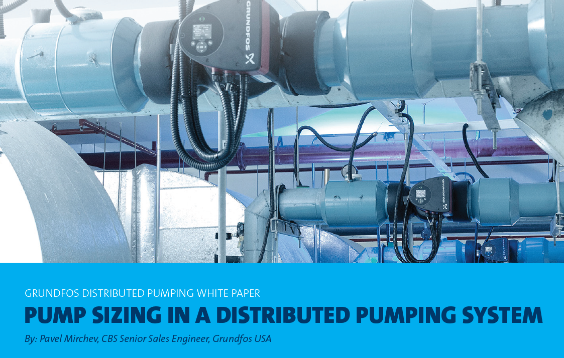
Distributed pumping is a hybrid pumping arrangement combining variable primary and variable secondary systems. ‘Distributed’ simply means the secondary pumps are distributed through the piping network to be located adjacent to each zone (coil pumps), specifically the air handling unit (AHU) or bank of fan-coil units. These distributed pumps will be installed in place of control valves and balancing valves. Primary pumps provide up to the full system flow and circulation through the bypass line, if necessary. Figure 1A shows a traditional variable primary design, and Figure 1B illustrates the same application, but with distributed pumps.

Figure 1A: Traditional Variable Primary Arrangement

Figure 1B: Distributed Pump Arrangement

Why use distributed pumps?

In conventional systems pumps are used to create the maximum pressure needed only by the furthest consumer in the system. Then balancing and control valves are used to restrict the flow through the rest of the consumers that do not require that maximum head, otherwise they will be over flowing. The pump duty point is going to move to the right, and the consumer that really needs the maximum head will not get it and will not be able to do the job it needs to. Distributed pumping eliminates the flow restricting balancing and control valves, replacing them with pumps that produce only the locally required flow and head. In this way it reduces the pressure requirements for the entire system, therefore reducing the pumping energy required to move the rated flow throughout the chilled water network. This reduction of pump energy results in overall pumping energy savings. The chilled water systems will also operate closer to the designed delta temperature of the system, resulting in increased efficiencies in chiller performance.

Primary Pumps in Distributed Pumping Systems

In traditional chilled water systems the primary pumps are sized for the full system flow and maximum pressure loss in variable primary systems, or for the full system flow, and pressure loss out to the bypass in a primary/secondary arrangement where the secondary pumps are sized for full flow and the maximum pressure drop through the secondary loop. In distributed pumping the primary pumps are only sized for pressure losses through the bypass in the mechanical room, along with full system flow. See Figure 2 for flow path of the primary pump.

Figure 2: Flow Path of the Primary Pumps

What happens if the full system pressures are removed from the primary pumps?

If the pressure losses for the full system are not required when selecting the primary pumps, you can drastically reduce the size of the pumps compared to a variable primary arrangement. In the case of primary variable secondary pumping arrangements, the primary pumps are sized for full system flow at constant speed, but only pumping against the pressures to reach the bypass line at the variable secondary. The sizing of distributed pumping primary pumps is done in a similar fashion, with the exception they are variable speed. These pumps can operate at constant speed like traditional primary pumps in a primary/secondary arrangement, but to maximize energy savings and delta temperature improvements, these pumps should be variable speed.

What about minimum flows through the chillers?

The first responsibility for the primary pumps in a distributed pumping arrangement is to insure there is minimum flow back to the chiller. The system utilizes an open free flowing decoupler so the primary pumps simply bypass flow to maintain minimum flows. If the minimum flows are satisfied, the primary pumps then will work to balance themselves with the secondary pumps.

Secondary Pumps in Distributed Pumping Systems

For systems utilizing variable primary pumps, no secondary pumps are required. In primary/secondary arrangements the secondary pumps are sized for full system flow and maximum pressure losses throughout the entire secondary network. Balance valves are then used to set the flow requirements for each zone or AHU. Since valves are flow inhibitors, each time this process takes place in a network, the pressure requirements for the secondary pumping system increases, which also increases pump horsepower requirements.

What happens when the secondary pumps are distributed?

When distributing the pumps into the piping networks in place of valves, a flow inhibitor is being replaced by a flow initiator, making the system as “free flowing” as possible. This process greatly reduces the friction losses in the piping network resulting in less horsepower to pump the secondary side of the system.

Are the distributed pumps sized the same as traditional secondary pumps?

Figure 3: Locations of the Distributed Pumps

The secondary pumps in a distributed pump network are located at each zone, specific to an AHU or a bank of fan-coil units. If the system has multiple zones, then it will require multiple distributed pumps. See Figure 3 for the location of the distributed pumps.

Since each zone requires its own pump, then that pump should be sized for the flow in that zone only as well as the friction losses through that AHU and the piping loop tracing back to the de-coupler. (See Figure 4, Page 4).

What are the key points to consider when determining the flow and head for the pump?

The flow for the distributed pump will be determined by the flow required for the specific zone it is supplying. The head calculation should include the losses through the AHU, check valve, and the friction losses of the supply and return piping loop from the decoupler to the pump. The friction losses of the piping should be determined for the worst case scenario – maximum system flow. This means if there is more than one zone connected to the system, the friction losses in the common supply and return line shall be determined by using the total flow of all the distributed pumps.

Will the pump cross flow into other zones?

Distributing the pumps in a chilled water network calls for removing the control valves and the balancing valves and replacing them with a pump. Without a control valve in place, the pump will be exposed to back flow when it is not operating. Because of this, a low resistance check valve is required for the discharge side of each distributed pump. This check valve will prevent back flow in the system. See Figure 4 for the location of each check valve.

How is the distributed pumping system balanced if there are no balancing valves?

The pumps auto balance the system. During commissioning, set the maximum pump flow for each of the distributed pumps based on the maximum flow for the AHU/zone being serviced. Doing this ensures the system will never be out of balance and will not require rebalancing after years of operation. The pumps will continuously readjust to changes in the equipment as the equipment ages, ensuring optimal operation throughout the equipment’s entire lifetime.

Figure 4: Piping Loop for Distributed Pumps

What additional inputs are needed to size a distributed pumping system?

Because distributed pumping delves further into overall system design, more information is needed beyond the traditional pump selections. For these applications Grundfos will need schematic layouts and equipment schedules. The items needed in the schematic are pipe details (diameter and length), fittings details and number of risers. These items can be estimated, but the more exact the information given during design, the more efficient the system will operate. The flow and pressure drops for the scheduled equipment (chillers, AHU, fan-coil units, etc.) are also needed.

Conclusion

Distributed pumping is an excellent way to improve your chilled water system efficiency. By removing the valves from the system and installing pumps in their place, a “free flowing” system is created, and the overall system pressure is reduced. This reduction of pressure results in less total system horsepower required to operate the system, while at the same time addresses the low delta temperature syndrome.

Visit grundfos.us/pei to learn more about Department of Energy (DOE) pump energy index (PEI) requirements and PEI ratings on specific Grundfos models.

LDPSWP01 0821

Trademarks displayed in this material, including but not limited to Grundfos, the Grundfos logo and “be think innovate” are registered trademarks owned by The Grundfos Group. All rights reserved. © 2021 Grundfos Holding A/S, all rights reserved.

DownloadView Source