IFMA Logo

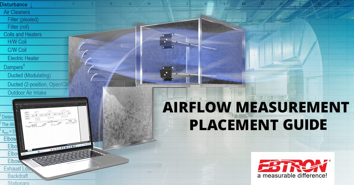
Ready to master the art of airflow measurement? Let this guide you to discover the ins and outs of placing airflow measurement devices. Unveil the perfect placement, whether in ducts or plenums and comprehend the design considerations that set your project up for success. Download the Probe Placement Guide and access the Probe Placement Tool by clicking the View Source button below.

Duct & Plenum Probe Placement Guide

A. OVERVIEW

This document provides guidelines for the proper placement of Advantage IV and EB-Flow2 duct and plenum mounted probes.

A.1. DESIGN CONSIDERATIONS

A.1.1. Installed vs. Laboratory Accuracy

The actual “installed accuracy” rather than “laboratory accuracy” is most important for overall system performance in real-world applications. As a result, EBTRON states field measurement performance expectations in terms of “installed accuracy”.

The installed accuracy is the expected accuracy at the measurement location and includes the sensor node error (sensor accuracy) stated in the model’s technical specification plus the expected field sampling error (additional inaccuracy that should be added to the sensor accuracy) that results from having a finite number of sensors across the sensing plane. Most instrumentation manufacturers ignore the sampling error, however, all multi-point sensing devices (airflow, temperature, humidity, etc.) have an error that results from the variable measurement profile across the plane where the sensor nodes are located.

  •  These guidelines are based on using EBTRON independently calibrated and processed thermal dispersion devices. Performance may vary on other thermal devices and/or measurement technologies.
  • If minimum placement guidelines cannot be achieved, installed accuracy may be compromised. Transmitters can be field adjusted to match a third-party measurement. Adjusted field measurements typically result in comparative readings within ±3% of the third-party measurement. Be advised that the third-party measurement may have uncertainties greater than or equal to ±10% (often greater on close-coupled outdoor air intakes) and should only be used to adjust the airflow measurement device if the probes do not meet minimum placement requirements and the discrepancy is greater than the uncertainty of the third-party source.

A.1.2. Duct Mounted Systems

Ducted measurement results in the most predictable performance and best installed accuracy compared to non-ducted or fan inlet measurement.

Duct mounting is typically applied to supply, return, relief, and outdoor air intake paths that have one or more equivalent duct diameter of straight run to locate the probes in. Close-coupled outdoor air intakes are discussed in the next section.

Installed accuracy expectations can vary depending on the model and sensor density. For example, high sensor density -PC and -P+ density probe types, and -T probe types (smaller round ducts), can achieve an installed accuracy of ±3% of reading in ducts when placement guidelines are followed. Lower sensor density -P probe types (-PE, -PB, -PA or custom) and -U probe types may have a lesser installed accuracy in the same measurement location as the -PC or -P+ densities, although all could perform similarly in a laboratory test tunnel having a minimal velocity profile.

A.1.3. Close-coupled Outdoor Air Intakes (CCOAI)

Close-coupled louver (or hood) and damper outdoor air intakes are perhaps the most challenging of all airflow measurement applications since both the upstream louver (or hood) and downstream damper can cause extreme velocity profiles and turbulence. These applications are most prevalent on recirculating air handling systems where an alternate path is not available to determine the outdoor airflow rate.

  • Locate probes on the discharge side of DOAS intake fan systems whenever possible.

Many air handling units have insufficient space in the outdoor air intake path to ensure accurate airflow measurement as a result of equipment footprint constraints. These constraints often result in a nonuniform velocity profile with extremely low airflow rates (less than 200 FPM). Dampers are often poor quality, oversized, and unable to modulate to control the design airflow rate. The use of parallel blade dampers to improve mixing adds to control instability in many applications. As a result, the highest performance airflow measurement equipment should be selected for the direct measurement of outdoor air intake flow rates.

Accurate measurement of outdoor air intake flow rates requires the following:

  • An adequate distance upstream of the damper is provided to avoid damper interaction (i.e., the damper position does not significantly affect the measurement of airflow).
  • An adequate distance downstream of the louver (or hood) is provided for the airflow to become partially developed.
  • The fan system does not create turbulence in the mixing box or eject recirculated air out of the outdoor air intake (too much return air).
  • The airflow rates are high enough not to be affected by transient wind gusts.
  • The airflow measurement device provided can measure the airflow rates over the entire operating range of the application.

The design of close-coupled outdoor air intakes varies considerably from manufacturer to manufacturer of air-handling equipment. This variability makes it difficult to present a clear and concise, “one size fits all”, placement procedure. EBTRON application specialists review tens of thousands of applications annually and are available at 1-800-232-8766 to assist customers and provide placement recommendations.

A.1.3.1. EFFECT OF THE OUTDOOR AIR INTAKE DAMPER ON MEASUREMENT

EBTRON testing indicates that minimal damper interaction measurement error results when the AMD is located one damper blade width upstream of the leading edge of a fully open, fully modulating, outdoor air intake damper. Test data is shown in Figures A-1 and A-2.

  • A lower airflow limit of 150 FPM is suggested so that transient wind gusts do not result in false readings in close-coupled applications. It is also recommended as the minimum velocity for effective control of modulating intake damper. IT IS NOT A LIMITATION OF THE EBTRON AIRFLOW MEASUREMENT DEVICE that can read down to still air (i.e., 0 FPM)
  • Provide a separate minimum intake damper, if possible, if the minimum airflow rate falls below 150 FPM.
  •  Do not apply this data to other technologies, including pitot array and other thermal dispersion devices. EBTRON thermal dispersion technology was specifically designed to perform in close-coupled outdoor air intake applications.
  •  Do not install the airflow measurement device downstream of a modulating or partially open damper!

Figure A-1 – 6” Opposed Blade Damper

Figure A-2 – 6” Parallel Blade Damper

A.1.3.2. EFFECT OF INTAKE LOUVERS ON MEASUREMENT

An installed accuracy of ±5% of reading or better can be achieved without field adjustment using either -P+ or -PC sensor density probes mounted downstream of an intake louver when the minimum distance and airflow rates indicated in Table A-1 are met or exceeded.

Louver design is extremely variable. Louver blades create significant blockage and turbulence that can adversely affect measurement accuracy. Table A-1 breaks down louvers into three general categories:

  • Stationary Louvers: ≥ 6-inch blade width
  • Stationary Louvers: <6-inch blade width
  • Hurricane/Rain Louvers

A.1.3.2.1. Stationary Louvers: ≥ 6-inch blade width

This category of louvers is the most common and most predictable for airflow measurement accuracy. This type of louver is most “transparent” and typically result in the best installed accuracy when leading manufacturers performance louvers are provided, even in close-coupled applications.

A.1.3.2.2. Stationary Louvers: < 6-inch blade width

This category of louvers is less predictable for airflow measurement accuracy since the free area is typically less than that of 6-inch louvers. The smaller blade size results in an increase in the number of fixed blades, thus resulting in more blockage and turbulence. The downstream distance required is greater than that of the 6-inch blade type for equal performance.

A.1.3.2.3. Hurricane/Rain Louvers

Hurricane, rain, and other high-performance specialty louvers are the least predictable for airflow measurement accuracy and often results in excessive blockage and turbulence. The downstream distance required is greater than that of the 6-inch blade type for equal performance. In many cases, field adjustment may be required.

A.1.3.3. EFFECT OF HOODS ON MEASUREMENT

Intake hood applications include both straight-through and radiused/angled hood types.

A.1.3.3.1. Straight-through Hoods

As a general rule-of-thumb, probes mounted in straight-through hoods have a better installed accuracy than angled or radiused hoods.

A.1.3.3.2. Angled (or Radiused) Hoods

Addition of an extension sleeve to a angled or radiused hood can improve the installed accuracy in some applications. However, field modifications are costly, and the actual benefit is difficult to predict. As a result, Table A-1 shows the expected installed accuracy, without field adjustment, for various hood configurations of angled and radiused hoods.

A.2. LOCATING PROBES (DUCTED SYSTEMS & CCOAI)

Step 1 - Determine the pressure relationship relative to the primary fan.

Determine which side of the primary fan the probe(s) will be mounted to establish whether it is a positive or negative pressure location relative to the air movement source. If the location is upstream (before) of a fan, the pressure relationship is typically negative, if it is downstream (after) of a fan, the pressure relationship is typically positive. In cases where the probes are located between two fans (examples: recirculated air or relief air), use your best judgement to determine the fan that is creating the primary air movement to determine the pressure relationship or contact EBTRON or your local representative.

Figure A-3 – Pressure Relationship Relative to Fan

Step 2 - Locate the immediate downstream disturbance in Table A-1.

Typical disturbances are found in Table A-1. Navigate vertically through the table to the immediate downstream disturbance at the measurement location you are considering. If the disturbance is not listed, contact EBTRON or your local representative.

Step 3 - Determine the corresponding figure for the downstream disturbance.

Once the downstream disturbance has been identified in Table A-1, navigate horizontally across the table to find the appropriate column based on the pressure relationship relative to the primary fan for the downstream dimension “Y”. The leftmost item in the column is the Figure ID. Determine the Figure ID and locate the corresponding figure in Table A-2 and note the reference point where the measurement is taken from.

Step 4 - Determine the minimum distance “Y” from the downstream disturbance.

Use Table A-1 to determine Ymin and Ycalc.

Ymin is a fixed value located in Table A-1 to the immediate right of the Figure ID for the Disturbance and PRESSURE SIDE OF FAN selected.

Ycalc is based on a multiple of the simple equivalent duct diameter, D, located in Table A-1 to the immediate right of Ymin, where,

The value for “Y” is the greater of Ymin and Ycalc.

 If there is no entry in Table A-1 for Ycalc, the value for “Y” is equal to Ymin.

Steps 5 to 9 apply to Ducted applications and CCOAI Louver and Straight-through hood applications only. Skip to Step 5R for CCOAI Radius/Angle Hood applications.

Step 5 - Locate the immediate upstream disturbance in Table A-1.

Navigate vertically through the table to the immediate upstream disturbance at the measurement location you are considering. If the disturbance is not listed, contact EBTRON or your local representative.

Step 6 - Determine the corresponding figure for the upstream disturbance.

Once the upstream disturbance has been identified in Table A-1, navigate horizontally across the table to find the appropriate column based on the pressure relationship relative to the primary fan for the upstream dimension “X”. The leftmost item in the column is the Figure ID. Determine the Figure ID and locate the corresponding figure in Table A-2 and note the reference point where the measurement is taken from.

Step 7 - Determine the minimum distance “X” from the upstream disturbance.

Use Table A-1 to determine Xmin and Xcalc.

Xmin is a fixed value located in Table A-1 to the immediate right of the Figure ID for the Disturbance and PRESSURE SIDE OF FAN selected.

Xcalc is based on a multiple of the simple equivalent duct diameter, D, located in Table A-1 to the immediate right of Xmin, where D is equal to the same value calculated in Step 4 (eq. A-1) and,

Xcalc = Multiplier · D

(eq. A-3)

The value for “X” is the greater of Xmin and Xcalc.

 If there is no entry in Table A-1 for Xcalc, the value for “X” is equal to Xmin.

Step 8 – Determine the distance “Z” between disturbances and the ideal location distance “L” from the upstream disturbance.

Refer to Figure A-4 and use the up and downstream figures in Table A-2 to determine the starting and ending reference points to determine the distance Z between the up and downstream disturbances.

Calculate the ideal distance “L” from the upstream disturbance:

(eq. A-4)

Step 9 – Locate Probes.

The distance “Z” between disturbances satisfies one of the following conditions:

  • Z is greater than or equal to X+Y
  • Z is less than X+Y

Choose the appropriate condition below to locate the probes,

“Z” is Greater than or Equal to X+Y

If Z is greater than or equal to X+Y, the location meets or exceeds the minimum placement guidelines, and the expected installed accuracy should result when the probe(s) are located anywhere inside of the Acceptable Area box shown in Figure A-5 (or distance L, when Z=X+Y). FIELD ADJUSTMENT IS NOT RECOMMENDED.

  • Locate the probes as close to the ideal location, distance “L” as possible to achieve the best installed accuracy.

Figure A-5

“Z” is Less Than X+Y (Ducted Applications Only)

If Z is less than X+Y, the location DOES NOT meet the minimum placement guidelines and the expected installed accuracy cannot be predicted. An alternate location is recommended. If an alternate location is not available, locate the probes distance “L” from the upstream disturbance shown in Figure A-6.

  • CCOAI Louver and Straight-through Hood applications that do not meet placement guidelines require special consideration. Refer to CCOAI Louver Straight-through Hood Applications below.
  • If minimum placement guidelines cannot be achieved, installed accuracy may be compromised. Transmitters can be field adjusted to match a third-party measurement (made in a better location). Adjusted field measurements typically result in comparative readings within ±3% of the third-party measurement. Be advised that the third-party measurement may have uncertainties greater than or equal to ±10% and should only be used to adjust the airflow measurement device if the probes do not meet minimum placement requirements and the discrepancy is greater than the uncertainty of the third-party source.
  •  Sensor probes located downstream of a modulating damper that do not meet placement guidelines may not be repeatable or accurate when the damper modulates, even if adjusted to match a third-party measurement. Do not install the airflow measurement device downstream of a modulating damper!

“Z” is Less Than X+Y (CCOAI Louver and Straight-through Hood Applications)

If Z is less than X+Y, the location DOES NOT meet the minimum placement guidelines and the expected installed accuracy cannot be predicted. Recalculate distance “L” using equation A-5 and locate the probes distance “L” from the upstream disturbance shown in Figure A-7 to avoid damper interaction error on the measurement.

L = Z- Y

(eq. A-5)

  • If minimum placement guidelines cannot be achieved, installed accuracy may be compromised. Transmitters can be field adjusted to match a third-party measurement (made in a better location). Adjusted field measurements typically result in comparative readings within ±3% of the third-party measurement. Be advised that the third-party measurement on CCOAI intakes may have uncertainties greater than or equal to ±25% and should only be used to adjust the airflow measurement device if the probes do not meet minimum placement requirements and the discrepancy is greater than the uncertainty of the third-party source.

 Do not install the airflow measurement device downstream of a modulating or partially open damper!

Steps 5R to 9R apply to CCOAI Radius/Angle Hood applications only.

Step 5R - Locate “Outdoor Air Intake Hoods” in Table A-1.

Step 6R - Determine the corresponding figure for the hood.

Determine the Figure ID and locate the corresponding figure in Table A-2. Note that the measurement is taken from the trailing edge of the radius hood.

Step 7R – Determine the distance “Z” between the hood and the outdoor air intake damper.

Refer to Figure A-8 to determine the distance Z between the downstream side of the hood and the leading edge of the fully open outdoor air intake damper.

Figure A-8

Step 8R – Determine the distance “X”

Calculate the distance “X”:

X may be less than 0.

(eq. A-6)

Figure A-9

Step 9R – Locate Probes.

Radius/Angle Hood applications are based on expected installed accuracy, without field adjustment, rather than minimum placement requirements to meet a single, expected installed accuracy. Locate probes distance “Y” upstream of the fully open outdoor air intake damper. Expected installed accuracy is as follows based on the distance “X” available:

Distance “X” Expected Installed Accuracy without Adjustment
X > 12 in. [305 mm] Better than or equal to ±5% of Reading
6” [153 mm] ≤ X < 12” [305 mm] Better than or equal to ±10% of Reading
X < 6 in. [153 mm] Better than or equal to ±15% of Reading (Installation in hood may be required)
  • Transmitters can be field adjusted to match a third-party measurement (made in a better location). Adjusted field measurements typically result in comparative readings within ±3% of the third-party measurement. Be advised that the third-party measurement on CCOAI intakes may have uncertainties greater than or equal to ±25% and should only be used to adjust the airflow measurement device if the discrepancy is greater than the uncertainty of the third-party source.
  • Addition of a sleeve between the hood and damper typically improves the installed accuracy.
  •  Make sure that a screen (if provided) does not interfere with probe placement!
  •  Do not install the airflow measurement device downstream of a modulating or partially open damper!

A.3. FOR MORE INFORMATION …

For toll-free factory support call 800-2EBTRON (232-8766), Monday through Thursday 8:00 AM to 4:30 PM and Friday 8:00 AM to 2:00 PM eastern time or contact your local representative.

TABLE A-1 SUGGESTED MINIMUM DISTANCES FROM UP AND DOWNSTREAM DISTURBANCES 1,2,3

1 This table is based on the immediate up and downstream disturbances and should be used as a guide. Additional nearby obstructions should be considered prior to selecting a location.
2 Call EBTRON at 800-232-8766 for disturbances not shown or for product application assistance.
3 Place the AMD beyond the absorption distance of humidifiers, evaporative coolers and other sources of water condensate. POSITIVE PRESSURE SIDE OF FAN RELATIONSHIP TO FAN → Upstream Downstream Disturbance Location Relative to AMD → NEGATIVE PRESSURE SIDE OF FAN Downstream Upstream
Choose greater of Xmin or Xcalc, where D = (Width+Height)/2 → Figure X Figure Y Figure X Figure Y
Xmin Xcalc Ymin Ycalc Xmin Xcalc Ymin Ycalc
Disturbance ↓
Air Cleaners
Filter (pleated) A-X-01 24" [610 mm] A-Y-01 6" [153 mm] A-X-01 18" [458 mm] A-Y-01 6" [153 mm]
Filter (roll) A-X-02 12" [305 mm] A-Y-02 6" [153 mm] A-X-02 12" [305 mm] A-Y-02 6" [153 mm]
Coils and Heaters
H/W Coil C-X-01 18" [458 mm] C-Y-01 6" [153 mm] C-X-01 18" [458 mm] C-Y-01 6" [153 mm]
C/W Coil C-X-01 18" [458 mm] C-Y-01 6" [153 mm] C-X-01 18" [458 mm] C-Y-01 6" [153 mm]
Electric Heater C-X-02 C-Y-02 Call EBTRON C-X-02 C-Y-02
Dampers4
Ducted (Modulating) D-X-01 D-Y-01 9" [229 mm]5 0.75D5 D-X-01 Call EBTRON D-Y-01 9" [229 mm] 0.75D
Ducted (2-position, Open/Closed) D-X-01 20" [508 mm] D-Y-01 10" [254 mm]5 D-X-01 20" [508 mm] D-Y-01 10" [254 mm]
Outdoor Air Intake
Call EBTRON Call EBTRON NA NA NA ≤1,250 FPM [6.35 m/s] D-X-01 D-Y-01 6" [153 mm]6 >1,250 FPM [6.35 m/s] NA Call EBTRON D-X-01 4 Distances are from the leading edge of a fully open damper blade when the damper is located downstream of the AMD and the trailing edge of when the AMD is located upstream.
5 The AMD may provide false readings as the damper approaches the closed position due to turbulence at the measurement location. 6 Xmin = Damper Blade Width
Elbows
Elbow (no turning vanes) E-X-01 36" [915 mm] 3D E-Y-01 18" [458 mm] 1.5D E-X-01 36" [915 mm] 3D E-Y-01 18" [458 mm] 1.5D
Elbow (turning vanes) E-X-02 9" [229 mm] 0.75D E-Y-02 9" [229 mm] 0.75D E-X-02 9" [229 mm] 0.75D E-Y-02 9" [229 mm] 0.75D
Elbow (radius or sweep) E-X-03 21" [534 mm] 1.75D E-Y-03 21" [534 mm] 1.75D E-X-03 21" [534 mm] 1.75D E-Y-03 21" [534 mm] 1.75D
Exhaust Louvers
Backdraft NA NA L-Y-01 30" [762 mm] NA NA NA NA
Stationary L-Y-01 18" [458 mm]
Fans (Ducted)
Centrifugal Fan F-X-01 24" [610 mm] 2D NA NA F-Y-01 12" [305 mm] 1D
Vane Axial Fan F-X-02 24" [610 mm] 2D NA NA F-Y-02 12" [305 mm] 1D
RELATIONSHIP TO FAN → POSITIVE PRESSURE SIDE OF FAN NEGATIVE PRESSURE SIDE OF FAN Upstream Downstream
Disturbance Location Relative to AMD → Upstream Downstream
Choose greater of Xmin or Xcalc, where D = (Width+Height)/2 → Figure X Figure Y Figure X Figure Y
Xmin Xcalc Ymin Ycalc Xmin Xcalc Ymin Ycalc
Disturbance ↓
Fan Plenums
Plenum to Duct P-X-01 18" [458 mm] 1.5D NA NA NA
Duct to Plenum NA NA NA P-Y-01 12" [305 mm] 1D
Outdoor Air Intake Hoods
Angled (or Radiused) Hoods
Installed Accuracy (without adjustment)
≤ ±15% NA NA H-X-01 0" [0 mm]7 NA
≤ ±10% NA NA H-X-01 6" [153 mm] NA
≤ ±5% NA NA H-X-01 12" [305 mm] NA
7 Install in Hood
Straight Through Hoods NA NA H-X-02 12" [305 mm] NA
Outdoor Air Intake Louvers8
Hurricane/Rain Louvers
<500 FPM [2.5 m/s] NA NA L-X-01 18" [458 mm] NA
500 to 1,250 FPM [2.5 to 6.35 m/s] NA NA L-X-01 24" [610 mm] NA
>1,250 FPM [6.35 m/s] NA NA L-X-01 36" [915 mm] NA
Stationary Louvers < 6" [152 mm]
<500 FPM [2.5 m/s] NA NA L-X-01 18" [458 mm] NA
500 to 1,250 FPM [2.5 to 6.35 m/s] NA NA L-X-01 24" [610 mm] NA
>1,250 FPM [6.35 m/s] NA NA L-X-01 36" [915 mm] NA
Stationary Louvers - ≥ 6" [152 mm]
<500 FPM [2.5 m/s] NA NA L-X-01 12" [305 mm] NA
500 to 1,250 FPM [2.5 to 6.35 m/s] NA NA L-X-01 18" [458 mm] NA
>1,250 FPM [6.35 m/s] 8 The expected accuracy can not be predicted if the AMD is located closer to the louver than suggested. NA Field adjustment may be required. NA L-X-01 24" [610 mm] NA
RELATIONSHIP TO FAN → POSITIVE PRESSURE SIDE OF FAN NEGATIVE PRESSURE SIDE OF FAN
Disturbance Location Relative to AMD → Upstream Downstream Upstream Downstream
Choose greater of Xmin or Xcalc, where D = (Width+Height)/2 → Figure X Figure Y Figure X Figure Y
Xmin Xcalc Ymin Ycalc Xmin Xcalc Ymin Ycalc
Disturbance ↓
Outdoor Air Intake Plenum to Duct9
<500 FPM [2.5 m/s] NA NA P-X-01 6" [153 mm] NA
500 to 1,250 FPM [2.5 to 6.35 m/s] NA NA P-X-01 12" [305 mm] NA
>1,250 FPM [6.35 m/s] NA NA P-X-01 18" [458 mm] NA
9 Maintain louver or hood minimum distance requirements to probe.
T Fittings
T Main Duct (no turning vanes) T-X-01 12" [305 mm] 1D T-Y-01 6" [153 mm] 0.5D T-X-02 18" [458 mm] 1.5D T-Y-02 6" [153 mm] 0.5D
T Main Duct (turning vanes) T-X-03 18" [458 mm] 1.5D T-Y-03 6" [153 mm] 0.5D T-X-04 12" [305 mm] 1D T-Y-04 6" [153 mm] 0.5D
T Branch Duct (no turning vanes) T-X-05 36" [915 mm] 3D NA NA T-Y-05 12" [305 mm] 1D
T Branch Duct (turning vanes) T-X-06 18" [458 mm] 1.5D NA NA T-Y-06 12" [305 mm] 1D
Terminal T (no turning vanes) T-X-07 36" [915 mm] 3D T-Y-07 12" [305 mm] 1D T-X-07 24" [610 mm] 2D T-Y-07 6" [153 mm] 0.5D
Terminal T (turning vanes) T-X-08 18" [458 mm] 1.5D T-Y-08 9" [229 mm] 0.75D T-X-08 12" [305 mm] 1D T-Y-08 6" [153 mm] 0.5D
Transitions
Reducing Transition Z-X-01 6" [153 mm] 0.5D Z-Y-01 6" [153 mm] 0.5D Z-X-01 6" [153 mm] 0.5D Z-Y-01 6" [153 mm] 0.5D
Expanding Transition Z-X-02 18" [458mm] 1.5D Z-Y-02 6" [153 mm] 0.5D Z-X-02 18" [458 mm] 1.5D Z-Y-02 6" [153 mm] 0.5D

TABLE A-2 PLACEMENT FIGURES – DUCTS AND PLENUMS

TABLE A-2 PLACEMENT FIGURES – DUCTS AND PLENUMS

Fig. ID: T-X-04 Fig. ID: T-Y-04
X Airflow Probe(s) T Main Duct (turning vanes) Y Probe(s) Airflow T Main Duct (turning vanes)
X Fig. ID: T-X-06 Probe(s) Airflow T Branch Duct (turning vanes) Fig. ID: T-Y-06 Probe(s) Airflow T Branch Duct (turning vanes) Y
Fig. ID: T-X-08 X Probe(s) Terminal T (turning vanes) Airflow Fig. ID: T-Y-08 Probe(s) Airflow Y Terminal T (turning vanes)
Fig. ID: Z-X-02 Airflow Probe(s) X Expanding Transition Fig. ID: Z-Y-02 Probe(s) Airflow Y Expanding Transition

TABLE A-2 PLACEMENT FIGURES – DUCTS AND PLENUMS

PlacementFIgures_Table_A-2_r3a

DownloadView Source